Usually, there is a deviation between the design parameters and actual parameters of a star sensor, so the parameters of the star sensors must be calibrated before use. The parameters that need to be calibrated mainly include the main point, focal length, and aberration.
(1) Main point calibration
The main point is the intersection point between the optical axis of the star sensor and the target surface. In parameter calibration, the main point must be calibrated before other parameters. Currently, there are two commonly used calibration methods:
This article uses a calibration method based on the principle of a centrifuge to calibrate the main point of the star sensor. The experimental steps of this method are: fix the star sensor lens upwards on a horizontal turntable, and a single star simulator forms a star point after imaging on the star sensor target surface. While rotating the turntable, observe the changes in the star point position on the target surface, and adjust the position of the star sensor in real-time so that the star point position on the target surface hardly changes during the turntable rotation. At this time, power is supplied to the star sensor and the star point coordinates on the target surface are extracted, You can obtain the main point coordinates of the star sensor. The advantages of this method are simple implementation and high calibration accuracy. After calibration using the above method, the main point coordinates of the star sensor are x=1025.14 and y=1022.89.
(2) Focal length calibration
This article calibrates the focal length using an outfield star observation method under a clear night sky. The experimental steps are as follows:
(3) Aberration calibration
This article uses the least squares partition fitting method to calibrate the aberrations of optical systems. After fixing the star sensor on a stable platform, level the platform, and then use the encoder value of the Leica theodolite (with an accuracy of 1 “) as the true value to calibrate the full field of view of the star sensor through imaging. Due to the differences in aberrations in different regions of the field of view, in order to ensure calibration accuracy, the field of view is divided into 9 regions for fitting, and the fitting coefficients of each region are obtained. Based on this, a compensation model for aberrations is established.
(1) Theoretical calculations
The single star measurement accuracy of star sensors is an important factor affecting the attitude measurement accuracy. The measurement error of a single star is determined by the angle measurement error of the star sensor and the system calibration error. The system calibration error is further divided into optical system distortion error, optical axis drift error, and system adjustment error. Below, the above parameters will be analyzed one by one:
(a) Angle measurement error
According to the formula, the angle measurement error of the star sensor is related to the field of view of the star sensor, the size of the image sensor pixel array, and the subdivision accuracy. The field of view of the star sensor in this article is 25 º × 25 º, the size of the image sensor pixel array is 2048 × In 2048, when the subdivision accuracy is 1/10 (usually 1/5-1/10), the angle measurement error of the star sensor is about 4.39 ″.
(b) System calibration error
The variation of the imaging center of the star point on the target surface of the image sensor results in optical system distortion error. In this article, the optical system distortion error is about 0.47 ″; The optical axis drift error is caused by factors such as deformation, vibration, and thermal stress of mechanical structures that may cause optical axis drift. In this article, this part of the error is within 2 “; System installation error refers to the system error introduced during the installation process of mechanical structures, optical lenses, and image sensors, which is within 1 “after calibration.
By using the theoretical calculation of the single star measurement accuracy of the star sensor, the attitude measurement accuracy of the star sensor can be estimated using the Hughes formula. The field of view of the star sensor in this article is 25 º × At 25 º, the maximum detection magnitude obtained through magnitude calibration is about 6.5Mv. According to Table 2.1, the average number of available stars is about 109. The average separation angle of the guiding star in the field of view is approximately 1/2 of the field of view, which is 12.5. The theoretical calculation value of the attitude measurement accuracy of the star sensor can be obtained through the formula.
(2) Experimental calibration
After theoretical analysis of the measurement accuracy of the star sensor, a one-dimensional (manually adjustable) precision turntable and a collimator were first used to experimentally calibrate the single star measurement accuracy of the star sensor. The experimental scheme will be introduced below.

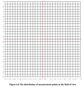
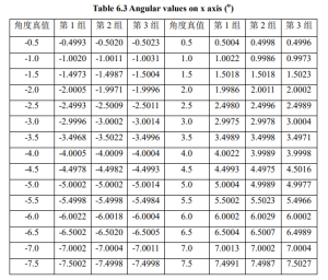
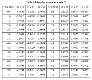
Fix the star sensor on a one-dimensional (manually adjustable) precision turntable with an accuracy of 0.5 ″ and level it. Use the parallel light emitted by the parallel light tube on the stable platform to simulate stellar starlight, and then use the star sensor to image the starlight. Firstly, image the star target on the x-axis, adjust the brightness of the light source to make the size of the star target at 3 × 3 to 5 × On 5 pixels, the target grayscale value is around 2000. Adjust the precision turntable to rotate in steps of 0.5 º, use a star sensor to extract the centroid coordinates of the star points, calculate the angle in the x-direction based on this, and compare it with the true value of the angle to obtain the angle difference. After completing the measurement in the x-direction, rotate the star sensor 90 ° and use the same method to measure the angle difference in the y-direction, completing a calibration of the single star measurement accuracy. The distribution of measurement points in the field of view is shown in Figure 6.6. The calibration experiment is repeated every 30 minutes, and the obtained experimental results are shown in Table 6 and Table 6.4.
Table 6.3 Angular values on x axis (º)

Table 6.4 Angular values on y axis (º)

After processing the experimental results in Tables 6.3 and 6.4, the average root mean square errors of the three sets of angle measurements in the x and y directions were 5.32 “and 5.29”, respectively, which are slightly greater than the theoretical calculation values of single star measurement errors. This may be due to random errors measured during the experimental process.
Usually, the attitude measurement accuracy of star sensors needs to be calibrated using a three-axis precision turntable. Due to experimental conditions, this paper approximates the attitude measurement accuracy of star sensors through field observation experiments under clear night sky. The experimental method is to fix the star sensor on a stable platform, and after power on, The star sensor images a fixed sky area and stores the measured attitude data to the main control computer. After the experiment, 1000 consecutive frames of attitude data were intercepted from the storage results of the main control computer, and the root mean square errors of attitude measurement data in yaw, pitch, and rolling directions were calculated. The results were approximately 3 “, 3”, and 20 “
Send us a message,we will answer your email shortly!