According to the adopted photoelectric sensor, star sensors can be divided into CCD (Charge Couple Device) star sensors and COMS (Comprehensive Metal Oxide Semiconductor) APS star sensors. The CCD star sensor uses CCD as the photoelectric converter, which has significant advantages in photoelectric conversion efficiency, sensitivity, and signal-to-noise ratio. However, CCD requires the design of complex peripheral driving circuits and video signal processing circuits. The advantage of CMOS lies in its high integration level, which eliminates the need to design peripheral driver circuits and image preprocessing circuits. At the same time, it combines the advantages of interface digitization and simplified power supply [5]. At present, the mainstream star sensors and the vast majority of photoelectric sensitive devices for star sensors with high precision requirements are CCD. A small number of star sensors with low precision requirements apply CMOS as image sensors. Star sensors using CMOS as photoelectric sensors have the characteristics of miniaturization, high integration, and low power consumption, which is also a development trend of future star tracker.
This article mainly introduces the CCD star sensor.
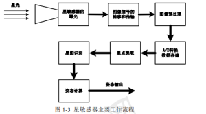
The working principle and process of a star sensor are as follows: first, the star sensor images the stellar light that enters the lens on the photosensitive surface of the CCD, converts the light intensity information into simulated charge information of the image. Then, under the joint action of the CCD driving circuit and related driving control signals, the simulated image charge signals are transferred out row by row, and after image preprocessing such as amplification, filtering, denoising, and correlated double sampling. Quantify the analog image voltage signal into a digital voltage signal using A/D conversion, convert the analog signal of each pixel into a digital signal, and then store it in a buffer register. After completing the above work, obtain the original digital star map data. Next, the microprocessor performs a series of processing on the digital star map, mainly including star point extraction, star map recognition, and attitude calculation, ultimately obtaining and outputting the attitude information of the star sensor at the time of shooting the star map.
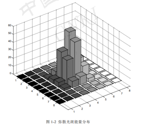
Star map requirements require an ideal star map to meet the following conditions: firstly, the number of stars absorbed in the map must be sufficient. Firstly, the sensitivity of the CCD must be sensitive enough to low magnitude stars, and secondly, the field of view must be large enough. This is determined by the size of the lens, focal length, and array size of the CCD. Secondly, the star points on the star map should be clear and free from “trailing” phenomena. This mainly requires the imaging quality of CCD, which requires low noise, high signal-to-noise ratio, and high sensitivity to shorten the exposure time and avoid the phenomenon of bright stars being too bright and trailing due to long exposure time. Once again, high accuracy, mainly due to the sufficient number of pixels in CCD, can achieve higher resolution. In addition, while ensuring the quality of the star map, the shooting and transmission rates should not be too slow, otherwise the attitude update rate will also slow down, reducing the attitude output rate of the entire system. The main principle of star point extraction is as follows: first, a global threshold is determined, and this threshold is used to segment the star point target from the background star map. Then, connected domain analysis is used to determine whether star point targets larger than the threshold belong to the same target. Then, a screening is performed on these merged star point targets to remove the oversized and undersized targets, leaving moderate star point targets. Later, due to the limited size of the image points, If the CCD happens to be located on the focal plane of the lens, the image of the star point on the CCD can only be one to two image points in size, resulting in limited accuracy in obtaining the star point coordinates. In order to obtain star point coordinates with better accuracy than one pixel, we can diffuse the star point into a light spot, so that the light energy of the star point can be distributed within a light spot with a radius of several pixels under certain distribution laws, By using interpolation and subdivision positioning algorithms, sub pixel precision star coordinates can be obtained. Figures 1-2 show the energy distribution of star points after star pattern stretching and dispersion. Star map recognition mainly involves matching the stars extracted from the star map, and then matching various matching patterns with the various patterns of stars in the standard star library to form a unique matching pattern for the observed stars with existing constant star pairs, thereby determining the coordinate information of the detected star points in the celestial coordinate system, and preparing for the next attitude calculation. The two indicators of star map recognition determine the accuracy and attitude update rate of star sensors. One is the accuracy of recognition. Only on the basis of accurately identifying the position of star points in the celestial coordinate system can the next step of attitude calculation have accurate reference vectors to accurately calculate attitude information. The second is the recognition rate, which will affect the time from “starlight in” to “attitude out” and also affect the rate of attitude update.
The main process of attitude calculation is to use existing observation star point vectors (at least two) and corresponding reference star point vectors (obtained through star map recognition), and then use static attitude determination algorithm to determine the initial attitude in the initial “LOST IN SPACE” state, and jointly capture the star map and attitude dynamics using dynamic estimation algorithm to estimate the attitude. Usually, the first step of star sensors in space is to initialize their attitude and begin to perform all sky sphere recognition. As only the observation vector information obtained from star map shooting is known at this time, the static attitude determination algorithm can only be used to calculate the attitude information of the star sensor at this time. This process is relatively slow in calculation, mainly because star map recognition, also known as “LOST IN SPACE”, has no known information, The recognition process will be slower. After this process, the tracking process is entered, and the process of local sky area recognition can be combined to use the captured star map information and attitude dynamics to estimate the attitude information through dynamic attitude estimation algorithms, thereby improving the attitude update rate.
Attitude determination methods can be divided into two categories:
One type is static determination algorithms, which mainly use vector observation information to determine the spatial position of star sensors, including TRIAD, Euler q, Quest, Foam (Fast optical attitude matrix), Least Squares (MLS), etc. Among them, the most widely used and influential is the Quest algorithm proposed by Shuster M.D.
Another type is dynamic estimation algorithms, which are not only limited to observed vectors as state variables and attitude parameters, but also include some uncertain parameters. The attitude determination system on modern spacecraft often uses multiple attitude sensors for combined measurement of attitude. According to the different ways of obtaining attitude angular velocity, attitude determination schemes can be divided into gyroscopic and gyroscopic schemes. The attitude angular velocity of the former is obtained from the rate integrating gyroscope, while the attitude angular velocity of the latter is obtained through attitude kinematics and attitude dynamics propagation.
This type of method mainly adopts Kalman filtering and various improved algorithms based on it, including Kalman filtering, Extended Kalman filtering algorithm (EKF), Nonlinear predictive filtering algorithm, Flat filtering algorithm (UKF), Predictive Kalman filtering algorithm, Adaptive Kalman filtering algorithm, Recursive attitude prediction method, etc. In recent years, such as particle prediction filtering algorithms, genetic algorithms, joint filtering algorithms, etc. have also been proposed. In the description of relevant literature, only the first four methods clearly indicate that only the observation vector information of star sensors can be used to estimate the attitude and angular velocity information of spacecraft. At the beginning, the extended Kalman filter algorithm was often used as an algorithm for spacecraft attitude determination and has been used in multiple space missions. Its state estimation values converged quickly and were not easily divergent. In the case of significant initial valuation errors, a certain estimation accuracy can still be guaranteed. However, its main limitation is the need to describe accurate kinematic and dynamic models. However, in practical situations, due to various interferences and measurement errors, it cannot be guaranteed that the given kinematic and dynamic models are sufficiently accurate, and there may be dynamic model errors that cannot be accurately described. The inaccurate description of the model equation can also lead to the inability to guarantee the accuracy of the extended Kalman filter, resulting in poor robustness and easy divergence. The Unscented Kalman filtering method based on the Unscented transformation uses the UT transformation instead of the linearization method, without the need to calculate the Jacobian matrix. The theoretical accuracy is higher than EKF, and the tolerance for initial attitude error is good. The main drawback is that the calculation is large, and the theoretical basis for selecting UT transformation parameters is insufficient. Both EKF and UKF assume that the random parts of the system follow a Gaussian distribution. However, for non gyroscopic attitude determination systems with strong nonlinearity, the errors of the attitude kinematics and dynamics models cannot be obtained in advance due to various interference noises, so the effectiveness of calculating the attitude cannot be guaranteed at this time. For the above issues, Crassdis and Markley proposed a nonlinear predictive filtering algorithm, which can effectively predict and estimate dynamic model errors. This method has been applied to attitude estimation on SAMPEX. But this algorithm is sensitive to the estimation error of the initial value and the noise of the measured value.


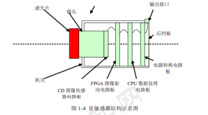
The structure of star sensors is mainly divided into two parts, optical system and circuit system. Specifically, it consists of a baffle, filter, lens, casing, baffle, CCD image sensor, image driver circuit board, CPU data processing board, power board, interface, etc. The overall structure diagram is shown in Figures 1-4:

The hardware design mainly adopts the scheme of DSP+CPLD. According to the structural characteristics of CPLD, it is more suitable for parallel processing and logical operations of logic signals, and is more suitable for obtaining suitable logic driving signals. However, DSP focuses on the calculation of digital signals, mainly contributing to the implementation of subsequent star map processing algorithms. Using CPLD to provide appropriate timing drive and control signals for CCD exposure. Use other image preprocessing chips to preprocess the transmitted image signal, such as amplification, filtering, correction, clamping, shaping, correlation double sampling to remove noise, etc. Apply DSP to achieve subsequent processing of star maps of collected digital signals. Implement software algorithms such as star extraction, star recognition, and attitude calculation in star maps, and then transmit attitude data.
The design of CPLD utilizes a hierarchical design method, using a combination of schematic diagram and VHDL language. The specific circuit diagram is shown in Figures 1-5.
The first part is the photoelectric conversion module, which mainly places the CCD sensor and its driving and signal transmission interface circuit to complete the photoelectric conversion of the optical signal and transmit the electrical signal outward.
The second part mainly includes the driver signal generation module. Mainly including CPLD chips and related configuration circuits, responsible for providing appropriate driving timing and control signals for CCD and driver chips, and performing some image preprocessing on the transmitted image signals, such as amplification, automatic gain control AGC, electronic aperture IRIS, gamma correction, blanking BLANKING, and related double sampling CDS.
The third part is the image signal processing part, mainly composed of DSP+CPLD and A/D conversion chips. The purpose is to perform A/D conversion on the analog image signal transmitted by CCD, and store the converted digital image signal in the memory. CPLD provides a synchronous sampling clock for the A/D conversion chip while assigning storage addresses to the converted digital star map data. Then, DSP is used to process the extracted digital image signal, and after star point extraction, star map recognition, attitude calculation, and other steps, attitude information is obtained, The motherboard is also equipped with an RS422 interface, which can communicate with the host to test the shooting function and image signal transmission function, as well as connect the star sensor to the star sky simulation device for simulation function testing.
The fourth part is the power supply, mainly composed of power components, which supply stable and appropriate voltage to various parts of the star sensor, so that the star sensor can work safely and reliably.
The technical indicators of the product are:
Field of view: 16 ° × 12 °
Area array: 670 × five hundred and twenty
Accuracy indicators: (yaw and pitch): 10 ″, rolling: 50 ″
Data update rate: 4Hz
Send us a message,we will answer your email shortly!