The technical scheme of a dynamic star simulator based on the LCOS optical splicing technology is proposed in order to meet the demands of a star sensor in spacecraft engineering. Optical system parameters of the simulator are calculated by the specification of a LCOS. The two LCOS optical splicing principle and scheme are introduced in detail, method of the dynamic star map realization is given, and its error is analyzed. The simulating results indicate that field of view is of 10.2° x 10.2°, star magnitude simulated is of 2~6.5, the single star field angle is less than 20″, and the star diagonal distance error is less than 22″. The experimental result can satisfy the system requirements of big field of view, wide magnitude range and update rate, etc.
With the continuous and rapid development of aerospace technology, the use of space optical attitude sensors for real-time attitude capture and measurement of spacecraft has gradually become a trend. Star sensors are high-precision attitude measurement equipment that obtain the attitude of spacecraft by observing the angular distance of stars. Therefore, the accuracy calibration of star sensors is very important. Due to the high cost of space experiments, star simulators have received in-depth research in recent years as ground calibration equipment for star sensors.
Star simulators can be divided into two categories based on their different functions: one is calibration equipment, also known as static star simulators. Star maps are immutable. These types of equipment usually simulate a single or limited number of star point images, and strictly simulate their size, magnitude, and spectral characteristics. Ground calibration is mainly carried out using the detection ability and spatial resolution of thousands of star sensors, with a focus on simulation accuracy
Another type is functional detection equipment, also known as dynamic star simulators, which can change the star map in real-time. Its characteristic is that it has strict requirements for the actual position of the star sky. The real-time performance of star map generation needs to match the working state of the star sensor. The essence of the problem is to check the effectiveness and correctness of the star map retrieval, position coordinate calculation and other functions of the aircraft, and to improve the accuracy of star map retrieval, coordinate conversion, and position calculation The position accuracy of star point generation has high requirements, and it can provide real-time and dynamic simulated star maps, that is, simulate the sky on the ground, in order to test the star map recognition algorithm of the star sensor. This type of star simulator has a complex structure and requires extremely high accuracy in the refresh frequency and inter star angular distance of the simulated star map.
The working principle of the dynamic star simulator is shown in Figure 1. The star simulator generates the star map data that can be observed by the star sensor at the current time based on the orientation of the star sensor coordinate axis in the inertial coordinate system provided by the attitude and orbit dynamics simulation calculation, and then generates the star map on the spatial light modulator (LCOS) through the interface and driving circuit. The light emitted by the simulated star point forms parallel light after being collimated by the optical system, Received by star sensor.

(1) Display star map resolution and LCOS determination
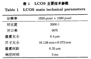
The field of view of the displayed star map is 10.2 ° X 10.2 °, and the single star angle is 20 “. Therefore, at least 1836 pixels should be displayed in both directions. The main technical parameters of the selected LCOS are listed in Table 1, with a pixel count of 1920 X 1080, which cannot meet the minimum pixel requirements. Therefore, it is decided to use the optical splicing method of two LCOS pieces.

(2) Determination of focal length for collimating optical systems
Determine the focal length of the optical system based on the simulated star map field of view and the total effective size of the selected LCOS. Given that the size of a single pixel in the LCOS is 8.4 μ M x 8.4 μ m. The total effective size after splicing is 16.128mm x l6.128mm, and the designed field of view of the optical system of the star simulator is 10.2 ° X 10.2 °
When using a single pixel as a star, considering that the opening rate of LCOS is 90%, the single star angle is 18.34 “, meeting the technical requirement of a single star angle of 20”.
(3) Design of LCOS splicing optical system
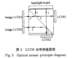
Due to the fact that a single piece of LCOS cannot meet the accuracy requirements of a high-precision star simulator, two pieces of LCOS need to be spliced. As shown in Figure 3, the splicing of the two pieces of LCOS is completed using a semi reflective and semi transparent polarization splitter prism (PBS). Among them, the semi reflective and semi transparent polarization splitter prism is composed of two 45 ° isosceles polarization right angle prisms bonded together. The two pieces of LCOS are symmetrically installed on their two sides with the semi reflective and semi transparent polarization splitter prism as the center.
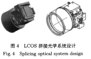
During the splicing process, it is necessary to ensure that the output energy of the two optical paths is the same while ensuring the splicing accuracy requirements, including overlap, straightness, and coplanarity. Figure 4 shows the mechanical structure of the splicing system.


1) Can sting requirements
It is known that the optical utilization rate of LCOS is 63%, and the transmittance and reflectance of PBS spectroscopic film are both 50%. The end face transmittance is set to 99%. As shown in Figure 3, the output light of path 2 is formed through 1 reflection and 1 transmission of PBS spectroscopic film, 3 side transmission and LCOSl reflection, with the highest output energy of 15.28%. The output light of path 3 passes through 1 transmission and 1 reflection of PBS spectroscopic film The output energy site formed by three side transmissions and LCOS2 reflections is also 15.28%. Therefore, the light emitted from the backlight plate passes through optical path 2 and 3, and the output energy site is exactly the same.
2) Lapping requirements
The pixels in the overlapping area should be strictly aligned to ensure a distance of 1000 LCOS pixels at the overlapping edge of LCOSl and LCOS2.
3) Straightness requirements
All pixels of the same level as LCOSl and LCOS2 must be on the same straight line
4) Coplanarity requirements
Coplanarity requires two LCOS to be installed at equal optical path positions after splitting, i.e. equivalent image planes
Using a polarizing beam splitter prism (PBS) to form a common plane with equal optical path, two LCOS are installed at the two equivalent focal planes of the star simulator, as shown in Figure 3. The light emitted from the backlight plate passes through the PBS prism and is divided into two optical paths: 2 and 3. PBS reflects the S light of the incident light (i.e. optical path 2) and transmits the P light of the incident light (i.e. optical path 3). After passing through LCOS, the S light becomes P light, At the same time as lighting up LCOSL, PBS emits P-light. Light path 3 passes through LCOS2, and while lighting up LCO-S2, S-light is reflected. The above scheme achieves the operation of lighting up two LCOSs with a backlight board. To improve stitching accuracy and reduce PBS size, the star simulator uses overlapping stitching technology to use the full image plane (1920 pixel x 1080 pixel) of LCOSL and part of the image plane (1920 pixel x 840 pixel) of LCOS2, After overlapping and splicing, the image size is 16.128mm x l6.128mm
(4) Design of collimating optical system
Due to the fact that the star sensor uses the energy centroid of the star image as the ideal reference for attitude positioning, strict requirements are placed on the optical system design of the star simulator device, which requires it to have small distortion, flat image field, and apochromatic aberration imaging quality. In addition, the larger field of view increases the difficulty of design. At the same time, the exit pupil of the collimating optical system should coincide with the entrance pupil of the star sensor and be of equal size, To ensure that the light emitted by various star points in the full field of view is the same as the total light flux of the sensor entering the pupil. In addition, there are polarized optical elements in the system, which can cause polarization aberration. Therefore, a telecentric system can be selected. The characteristic of this system is that the main light rays are parallel to the kilo optical axis, and the average polarization aberration is equal to each field of view. At the same time, the degree of polarization is controlled by controlling the angle of the light rays incident on the polarization element, which can ensure that the degree of polarization of each field of view is minimized, And the uniformity of color and energy address is good, even if the star simulator shifts along the axis, it will not affect the measurement accuracy. The frequency band of this system is 0.47~0.76 μ m. Center wavelength input=0.62 μ m. Design for correcting aberrations in both edge and center bands
The simulated star point position in the field of view of the star sensor can be solved by the position of the navigation star in the celestial inertial coordinate system and the declination of the optical axis of the star sensor and the X-axis of the CCD plane in the inertial coordinate system provided by the main computer of the system experiment
For star sky simulation, it is equivalent to displaying a two-dimensional digital image. In addition to coordinate values, it is also necessary to obtain the grayscale value of each pixel. The smaller the magnitude value, the stronger the corresponding brightness, and the larger the corresponding grayscale value. Therefore, the magnitude can be simulated by changing the grayscale value of the star points. The specific method is to use a star simulator to control the computer to change the grayscale value of the star points on the LCOS LCD screen to simulate the magnitude. Several pixels are used as a single star point display to change the grayscale value of the star points and simulate the magnitude. During programming, the equivalent value of the star points is reflected by the grayscale value, and the range of known grayscale value changes is 0-255. When the grayscale value is set to 255, a second-class star is simulated. Due to the difference in the brightness value for every 1 difference in the magnitude number, the brightness value can differ by 2.512 times.
Using the existing optical splicing scheme, the accuracy of the main technical indicators of the star simulator is related to the unit angular resolution, optical system correction error, splicing error, correction error, star table settlement error, and the docking adjustment accuracy with the star sensor during use.
Using LCOS as the core device and optical splicing method, high-precision usage requirements were achieved. Based on the selected LCOS device, parameters such as the focal length and single star angle of the star simulator optical system were calculated and analyzed. The working principle of the optical splicing method was explained to design a star simulator optical system that meets the requirements. The structure and aberration curve of the star simulator optical system were provided to achieve dynamic star map simulation. Finally, The error of the system was analyzed. The field of view that the star simulator described in this article can simulate is 10.2 ° X 10.2 °, with magnitudes ranging from 2 to 6.5. The single star angle is better than 20 “, and the star diagonal distance error is 22” lower. This can meet the requirements of wide magnitude range, large field of view, and fast update rate for star simulators in aerospace engineering.
Send us a message,we will answer your email shortly!