Understanding astronomical knowledge about star sensors can help us understand product characteristics.
Ancient astronomers believed that the position of stars in the sky was eternal and unchanging, and called them stars. In fact, stars are not ‘constant’, they are constantly undergoing large-scale and small-scale movements, and each has its own evolutionary history. Normal stars evolve slowly, resulting in very small changes in brightness. However, due to their distance from us or their orbits being in a straight line from our viewpoint, these movements have already been reduced to a point when they enter our eyes, making it difficult for us to observe their position changes.
The spatial motion of a star refers to its motion relative to the sun. This movement can also be divided into coming towards the sun, going away from the sun, running to the left, and walking to the right. The spatial motion velocity of a star is divided into two components: the tangential velocity perpendicular to the direction of the line of sight; The direction consistent with the line of sight is called visual velocity. The apparent velocity is further divided into two types: coming towards the sun and going away from the sun. We see the angular distance of the star’s annual movement on the celestial background, known as its own motion. Stars have rotational motion, mutual motion around a common center of gravity, and spatial motion. This article adopts the standard model of stellar motion used in the Hipparcos catalog.
The standard model of stellar motion assumes that the motion of stars in the International Celestial Reference System (ICRS) is a uniform spatial motion relative to the center of gravity of the solar system. From the perspective of the center of gravity of the solar system, ignoring the displacement caused by parallax, the motion trajectory of a star on the celestial sphere is a large arc. At a certain reference epoch T=T0+t, the motion of a star can be determined by the right ascension α 、 Declination δ 、 Parallax π, right ascension self µ α* 、 Declination self motion µ δ There are a total of 6 astronomical parameters to describe with the visual velocity VR.
(1) Simple epoch conversion
The simple epoch conversion formula for converting the celestial position of a star from epoch T0 to any epoch T in the catalog does not accurately describe the standard motion model of a star on the celestial sphere. This model describes a curve that spirals towards the celestial pole, while in fact, in the standard motion model, stars move along a huge arc. Although the difference between the two is small compared to precision epoch, it can be significant in special circumstances, especially when approaching the celestial pole or with long epoch time intervals. Therefore, simple epoch conversion is not suitable for use in precision attitude determination.
(2) Precision epoch conversion
In the standard model of stellar motion, it is assumed that the motion of a star is uniform in space, and the trajectory of the star on the celestial sphere is a large arc. The angular velocity (self motion) of a star along this large arc is variable, and its maximum self motion occurs when the star moves along its orbit at perihelion; Its distance (parallax) and visual velocity also vary. The changes in right ascension, right ascension, parallax, right ascension motion, right ascension motion, and visual velocity (6 astronomical parameters) must be considered during precise epoch conversion.
(3) Epoch conversion error propagation
According to the standard model of stellar motion, the Hipparcos catalog provides five astronomical parameters (right ascension, right ascension, parallax, right ascension self motion, right ascension self motion) vectors a and their covariance matrix C. Where vector a is 5 × 1-dimensional, matrix C is 5 × 5 dimensions. Estimate 5 variables using the weighted least squares method, and based on the least squares estimation, all estimated information is included in 5 × In the covariance matrix of 5, the matrix elements and the elements of the variance covariance matrix are composed of the standard deviation and correlation coefficients of the estimated parameters;
Statistically speaking, the vector a and covariance matrix C together describe the numerical fitting of the standard model of stellar motion, with uncertainty solely due to linear estimation relationships and standard (Gaussian) deviation distributions. In the analysis of Hipparcos and Tycho data, the estimation problem is rarely strictly linear, but in the vast majority of cases, the vector a and covariance matrix C provide very useful fitting approximations.
When discussing the attitude of a satellite, the first step is to select a spatial reference coordinate system. At least two coordinate systems need to be established to strictly determine the satellite’s attitude, one is the spatial reference coordinate system, and the other is the star coordinate system fixed to the satellite. The angular relationship between the three coordinate axes of the star coordinate system and the reference coordinate axis describes the satellite’s attitude. In practical use, two coordinate systems are not enough because the measurement axis of the attitude sensor is not always consistent with the selected star coordinate axis. It is necessary to convert the measurement coordinates to connect the star coordinates with the spatial reference coordinates.
(1) International Celestial Reference System (ICRS)
The definition of ICRS is based on the reference system recommended by the 1991 IAU. The accuracy of the coordinate axis of the coordinate system is ± 30 µ as. The direction of the ICRS coordinate axis is consistent with the FK5 (bisector equatorial J2000.0) coordinate system, where J2000.0 has (± 50-80 mas; E.F. Arias, P. Charlot, M. Feissel&J.F. Lestrande, 1995, Astronomy&Astrophysics, 303, 604) uncertainty, and the difference between the ICRS coordinate axis and the current FK5 dynamic reference system is ± 3 mas (W.M. Folkner, P Charlotte, M.H. Finger, J.G. Williams, O.J. Sovers, X X Newhall&E.M. Standish, Jr., 1994, Astronomy&Astrophysics, 287, 279). ICRS ensures that the continuity during the conversion from FK5 to ICRS is not greater than the uncertainty of FK5 itself. With the adoption of ICRS and the customary definition of celestial coordinate systems, the equatorial plane and ecliptic plane have lost their importance in the basis of celestial reference systems. Therefore, in addition to specifying the right ascension in this coordinate system α Declination δ Outside the origin of the ICRS, it is no longer meaningful to say ‘equator’ or ‘equinox’. Specifically, there is no specified date corresponding to the ICRS right ascension α The origin, although it is very close to the translational bifurcation of J2000.0.
(2) IBAGU reference frame HRF
The position given in the Ebaco catalog effectively defines the celestial coordinates of epoch J1991.25( α ,δ ) Grid. The catalog also provides the self motion of stars, allowing the grid to move forward or backward to any epoch (although adding uncertainty to different epochs). The position and self determination in the Ebaco catalog define a reference coordinate system – the Ebaco reference frame HRF, which achieves positional and self determination accuracy of 0.1 mas and 0.1 mas/yr at J1991.25 on a global scale. The Ibaco catalog is constructed within the framework of the Ibaco reference frame, consistent with ICRS under limited observation uncertainty. The Ebagou reference frame can exist independently as a realistic version of ICRS, and in the following years, it has always been the optimal implementation of ICRS in the optical field. The Ibago catalog uses the International Celestial Reference System (ICRS) instead of the FK5 coordinate system. From the perspective of optical astrometry, the Ebaco catalog can be seen as an extension and improvement of J2000.0 (FK5), still retaining the global positioning accuracy of J2000.0 and avoiding regional errors.
(3) Yang center inertial coordinate system SCI
People always hope to use an inertial coordinate system because it makes it easier to compare observations with theory. The heliocentric coordinate system is a good approximation of the inertial coordinate system [90]. The origin of the yang center inertial coordinate system is at the center of mass of the sun, and the coordinate axis symbol (Xsci, Ysci, Zsci). The X-axis points towards the vernal equinox, the Z-axis is the normal direction of the ecliptic plane, and the Y-axis is perpendicular to the X-axis on the ecliptic plane, forming a right-handed coordinate system (as shown in Figure 2.2)
Figure 2.2 Positive center internal coordinate system

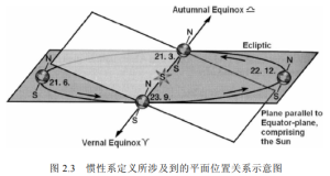
The vernal equinox is defined by the intersection of the Earth’s orbital plane and the Earth’s equatorial plane. In autumn, when the sun is located in both planes and the vector from the sun to the Earth is consistent with the vector from the sun to the equinox, the point is called the vernal equinox, as defined in Figure 2.3. Due to the precession of the Earth’s rotational axis, there is a periodic time-varying direction of the three axes of the inertial system, which is approximately 26000 years.
Figure 2.3 Schematic diagram of the plane position relationship involved in the definition of internal frames

(4) ECI (Equatorial Cartesian Coordinate System)
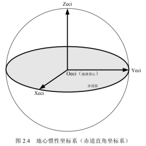
The origin of the geocentric inertial coordinate system is at the Earth’s center of mass, with the coordinate axis symbol (Xeci, Yeci, Zeci). The X-axis points towards the vernal equinox along the intersection of the Earth’s equatorial plane and the ecliptic plane (as shown in Figure 2.3), the Z-axis points towards the northern celestial pole, and the Y-axis is perpendicular to the X-axis on the equatorial plane, forming a right-handed coordinate system (as shown in Figure 2.4).
Figure 2.4 Geocentric Industrial Coordinate System (Equatorial Cartesian Coordinate System)

If there is no special explanation, the inertial coordinate system refers to ECI. The coordinate origins of SCI and ECI reference frames are different, especially when used in SCI catalogs, the difference in coordinate origins can cause changes in the apparent position direction of stars.
(5) Image plane coordinate system
The origin of the coordinate system is in the upper left corner of the imaging surface, with the X axis perpendicular to the Y axis, and its direction is shown in Figure 2.5. The origin of the coordinate system is in the upper left corner of the imaging surface, with the X axis perpendicular to the Y axis, and its direction is shown in Figure 2.5.
Figure 2.5 Image plane coordinate system

(6) Star sensor coordinate system (ST)
The coordinate origin OST is the center of the imaging plane (x0, y0), and the coordinate axis symbol (XST, YST, ZST). The X axis of the ST coordinate system is parallel to the X axis of the image plane, with opposite directions, while the Y axis is parallel to the Y axis of the image plane, with opposite directions. The Z axis is obtained by multiplying the X axis and Y axis, and coincides with the optical axis of the star sensor (as shown on the right in Figure 2.6). The star sensor coordinate system is fixed in the star coordinate system, and its exploded view with the image plane is shown on the left in Figure 2.6.
Figure 2.6 Star Sensor Coordinate System

(7) Stellar coordinate system
The celestial coordinate system is fixed on the satellite, with the origin of the coordinate coinciding with the satellite’s center of mass, and the coordinate axis symbol (Xsat, Ysat, Zsat). The direction of the coordinate axis is given by the satellite attitude control system and is related to the three attitude angles of the satellite, namely pitch, roll, and yaw. It is a coordinate system related to the satellite attitude.
There are various forms of attitude parameters, the most general of which is the directional cosine between the ontology coordinate system and the reference coordinate system. This method is not intuitive and lacks clear geometric image concepts. The Euler angle of rigid body rotation is commonly used to represent the satellite attitude, but Euler rotation has singularities, so attitude quaternion equations are generally used. Due to the unique determination of satellite attitude, various attitude parameters can be converted to each other.
(1) Directional cosine equation
(2) Euler angle equation
According to Euler’s theorem, the displacement of a rigid body around a fixed point is a combination of several finite rotations around that point. In the process of attitude control, the Euler angle formula of attitude has a simple and obvious geometric significance, and its convenient control makes it widely used. The attitude matrix determined by Euler angle is the product of three coordinate transformations. This article adopts a rotation order of 3-2-1, which is to first rotate the yaw angle around the z-axis, the coordinate transformation matrix is R (yaw), then rotate the pitch angle around the y-axis of the new coordinate system, the coordinate transformation matrix is R (pitch), and finally rotate the roll angle around the x-axis of the new coordinate system, and the coordinate transformation matrix is R (roll). According to the standard formula of the coordinate transformation matrix, the attitude matrix A (yaw, pitch, roll) is obtained.
(3) Euler axis/angle parameterization
According to Euler’s theorem, any displacement of a rigid body around a fixed point can be obtained by rotating it through an angle around an axis passing through that point. There are four parameters for describing attitude in the Euler axis/angle parameterization: the unit vector e of the rotation axis, the cosine of the three directions in the reference coordinate system, and the rotation angle around this axis Φ 。 The attitude matrix formula described by these four attitude parameters.
(4) Euler quaternion equation
In order to facilitate matrix operations on the attitude matrix, four additional attitude parameters are composed of the Euler axis/angle parameterization. The first three represent the direction of the Euler axis, and the fourth represents the Euler angle. The quaternion q defines these four parameters as satisfying the constraint equation.
Send us a message,we will answer your email shortly!